Dissecting the Nut Factor
by:
Dave Archer | Principal Engineer
Peak Innovations Engineering
9934 N. Alpine Rd., Suite 104
Machesney Park, IL 61115 USA
A RIDDLE, WRAPPED IN A MYSTERY, INSIDE AN ENIGMA
It is recognized we measure torque when tightening threaded fasteners only because measuring bolt tension, the more important quantity is much more difficult. The relationship between the torque applied to a fastener and the tension created from the resulting bolt elongation is most commonly described by T = F*K*D where T is torque, K is the nut or friction factor (nut factor for this article), D is the bolt diameter and F is the bolt tension or preload. Less common is a discussion of how this equation was derived, in particular the origin of the nut factor. Because this single variable K determines the critical torque-tension relationship, the factors that cause its value to vary about 300% across a range of common applications are not clear. Examining the sources and relative sensitivity of these factors is the subject of this column.
The nut factor, as defined in the above equation (often called the short form relationship), is, in reality, a factor not derived from engineering principles but instead arrived at experimentally to make the equation valid. Various published torque-tension test procedures call for tensioning a threaded fastener in a controlled manner while monitoring both torque and tension. At the specified torque or tension, the nut factor is calculated by inserting T, D, and F in the short form equation and solving for K.
Given this rather unsophisticated origin, one may be surprised to know there are a number of published torque-tension relationships derived from engineering principles. They produce similar results to one another and take the general form T=F*X, where X is a placeholder for a series of terms containing variables of fastener geometry and friction coefficients. Three of the most widely-used examples are shown below. While at first glance they may appear to be quite different from one another, they are actually different forms of the same relationship and produce the same results.
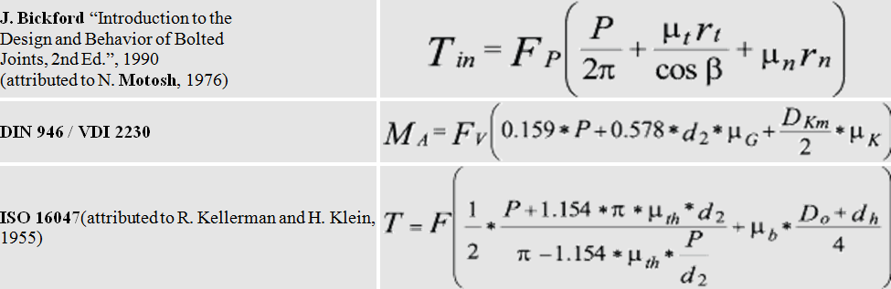
Where
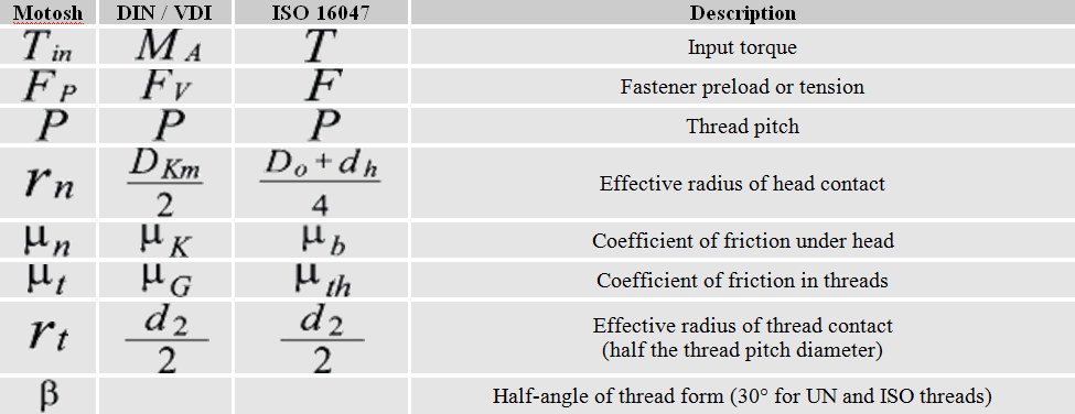
To understand what factors influence the relationship between torque and tension we will review the variables in these equations and quantify their relative influence. The Motosh equation is easiest to understand for most people so we will base our discussion on its format. Each term within the bracket calculates a length when multiplied by the force generated by bolt tension (Fp) results in a torque. So each term is a reaction torque that resists the input torque Tin, and their sum must be equal to the input torque. The first term produces the clamp load due to the inclined plane produced by the thread pitch.
The second term is the resisting torque caused by thread friction and the last term is a similar resting torque caused instead by friction between the nut or head face (whichever is rotated) and the mating surface. Therefore the value of each term indicates the relative influence of the variables in each term. For example, solving for an M12-1.75 flange head screw with 0.15 friction coefficients produces values of 0.28 N-m, 0.93 N-m, and 1.35 N-m for each kN of tension. This breaks out to 10.9%, 36.3%, and 52.8% of the 2.56 N-m total, and illustrates the common comment that “only about 10-15% of input torque goes toward stretching the bolt”.
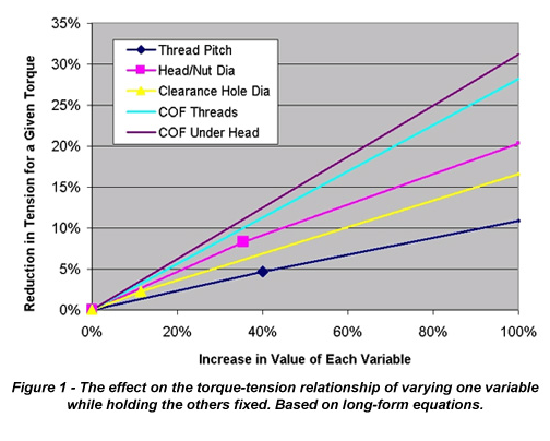
How do our design decisions influence the torque-tension relationship? To answer that, Figure 1 shows the effect of doubling the value of each variable in the short form equation while holding the others fixed. It shows that if the thread friction coefficient was doubled while the other variables remained the same, the bolt tension generated for the same installation torque would decrease by about 28%. While friction coefficients occur on a continuous spectrum, the dimensions of standard fasteners and accompanying clearance holes tend to be discreet. To illustrate, Figure 1 also contains three points showing the effect of the following design alternatives; replacing a fine pitch thread with a standard pitch, replacing a hex head with a hex flange head, and replacing a close diameter clearance hole with a large diameter hole.
For example, replacing a hex head fastener with a hex flange head (but not changing friction coefficients, thread pitch, or hole diameter) increases the bearing diameter by about 35%, which in turn will cause bolt tension to be reduced by about 8% for a given torque. While these values vary a bit with fastener size, the relative importance of each variable will remain the same.
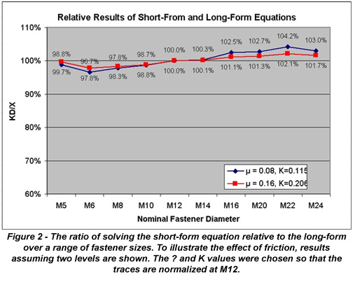
We are sometimes asked the question. “If we perform a torque-tension test with a particular fastener diameter to calculate nut factor, do those results apply to other diameters, assuming all other conditions are the same?” In fact, the nominal diameter is separated from the nut factor in the short form equation for just that reason, so that test results can be scaled to other fastener sizes. Is this an assumption based on engineering principles? Actually, it is only an approximation, as none of the terms in the long-form equations contain the nominal diameter as a variable. Therefore, the accuracy of using the nominal fastener diameter D as a means of applying a constant nut factor across all fastener sizes is dependent on whether the affected variables in the long-form equations vary in direct proportion to the nominal diameter. The answer is shown in Figure 2 where the long-form equation is solved for standard pitch metric hex head cap screws with constant and equal coefficients of friction.
The traces, normalized at M10-1.5, show a 4.2% maximum deviation between the short and long-form equations, decreasing as the friction coefficients increase. The variable with the greatest relative deviation from nominal diameter through the range of fastener sizes is the thread pitch, as the pitch is somewhat arbitrarily selected, while the dimensions of the thread form and the clearance hole diameter are all directly tied to the nominal diameter. Because the first term containing the pitch diameter does not contain a friction coefficient, as friction increases the relative importance of pitch is decreased, and therefore the fact that pitch does not vary directly with nominal diameter has less impact on the result of the torque-tension calculations.
Therefore, holding all else constant, applying a nut factor that was calculated at one diameter across a range of fastener sizes is a reasonable assumption. For best results, the weighted mean diameter of the fasteners on which the nut factor will be used should be the basis of testing. In reality, most organizations apply nut factors across a greater set of conditions. For example, fasteners may not have the same head style or clearance hole diameter. When a constant nut factor is applied to joints where geometry variables other than nominal diameter are changing, calculated deviations of 15% can occur between short and long-form equations even for standard geometries.
These comparisons using nut factor relative to the long-form relationships may imply that these impressive-looking equations produce the “right” answer due to their fundamental correctness. This is in fact not true, as the assumptions and approximations inherent in their derivation. However, the potential error of these assumptions pales in comparison to the variation that exists in real-world joints. As an example, Figure 3a shows the result of torque-tension testing on the bench-top setup and controlled test conditions specified by published test methods. Even though all fasteners and bearing materials are the same for each test, and are actually swapped out for fresh ones, there is approximately a 10% variation within the group. According to both the short and long-form equations, there should be no variation at all. Figure 3b shows a similar graph generated from in-torque-tension testing.
Using ultrasonic pulse-echo techniques bolt tension can be measured in real-time in the actual joint without altering joint characteristics. The graph shown reflects the dynamic torque-tension relationships of a single assembly with a circular six-bolt pattern. The variation inherent in how components actually fit one another adds another source of torque-tension variation on top of the variation seen in the benchtop test. The variation in Figure 3a is primarily due to the fact that the friction coefficients for each sample were in reality not identical. The extreme 60% variation seen in Figure 3b occurred because the joint configuration magnified the effect of imperfect contact. This results in changes to both the geometry and friction variables.
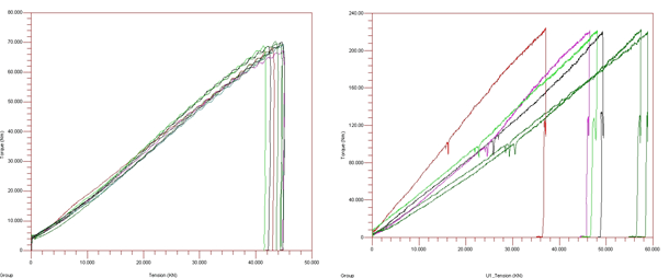
Figure 3a,b – Results of Torque-Tension testing on an exemplar joint (left), and in an actual joint through the use of ultrasonic pulse-echo technology (right).
These examples illustrate why the relationship between torque and tension can only be accurately determined through testing, where both the mean and distribution about that mean can be determined.
While the nut factor K is the most popular means of quantifying the torque-tension relationship in the U.S., in Europe, or within organizations that design strictly to ISO or DIN standards, the long-form equations are utilized. Because separating thread and head friction significantly limits the test equipment that can be used and eliminates the potential for in-joint testing with actual components, it is common to make the assumption that both under-head and friction coefficients are equal (ISO 16047 estimates a 1%-2% error for this assumption).
Using ISO designations, the long-form equivalent of K is shown below to the left of the short-form arranged to solve for K. The VDI/DIN designation for µtot is µges Because the terminology used when describing µtot and K are similar (friction factor, friction coefficient), errors are sometimes made by unknowingly substituting one for the other. As shown in Figure 2, to arrive at the same result the value of K is approximately 35% greater than µtot.
The ability to predict the tension in a threaded fastener for a given torque input is largely a function of understanding the friction present between mating surfaces containing relative motion. Only testing can accurately determine these friction conditions, which are so sensitive to component variation only in-joint testing can determine the relationship when controlling bolt tension is critical. Organizations calculating the nut factor K in testing may want to consider the simplified long-form equations (friction coefficients assumed equal) for greater sensitivity over a range of applications, particularly when more than nominal diameter is expected to vary.
Company Profile:
Peak Innovations Engineering has a highly technical team to design, test, validate, and enhance the bolted joints within your product application. Joint development and testing are all we do, so we do it better than other available options, both internal and external. Why consume your resources in engineering and problem-solving areas that are secondary to your core responsibilities when we can take care of them quickly, definitively, and cost-effectively? www.pieng.com